Next: User-Functions Up: CalculiX USER'S MANUAL - Previous: Weighted Error Contents
If a tet mesh is required and the user meshes at first the surfaces and then generates the tet elements using the command “mesh 'setname' tet” only the 'setname' and the set 'all' reference the tet elements and the newly generated additional nodes!
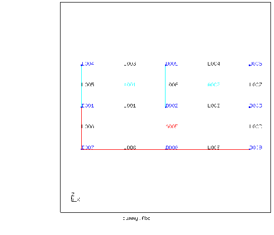
The way the mesher works has the consequence that only bodies who share a single common surface are connected at each node were they touch each other. Three surfaces with their points and lines are shown in figure 11. When sweeping this surfaces in 'y' direction three bodies will be generated. The line L006 generates a surface between the bodies at the position of A001 and A002. Both bodies will reference this surface and will therefore share its nodes. So all elements will be connected at that location. But a body using the surface A005 will use a surface generated by the combined line of L001 and L002 extruded in 'y' direction! This surface will not be used by the bodies generated by A001 and A002 since they will use the surfaces generated by the separately extruded lines L001 and L002. So bodies at the position of A001 and A005 will share the nodes of the common lines and points but not of the new surfaces at the location of line L001 (and not at the location of the new line at point D002). In the end at some inner locations gaps will exist.
Some rules must be fulfilled before a geometry is meshable (see mesh). For linear elements (ie. qu4 or he8), the sum of all divisions (see div) of each surface must be even. In case of quadratic elements (ie. qu8 or he20) this sum must be divisible by 4 without residue. Opposite edges of a given surface might have different divisions. For example on the left side of a given surface the division is 8 and on the right side it is only 4. But only two opposite surfaces of a body can use this feature. These surfaces are called top and bottom surfaces. All other surfaces of this body must have unique divisions on opposite edges. In case of 3 sided surfaces it is necessary to apply a minimum division sufficient for two elements along the edge. The only exception is the element tr3u (see elty) which allows a division of one.
A body can not be meshed when the shape of the body is very far from being brick-like. The body might be subdivided to improve the shapes of the single ones. There is a restriction for the definition of five- or seven-sided bodies. The first two surfaces in the body-topology (see gbod) have to be defined in the same order. That means the first line of the first surface has to be connected with the first line in the second surface by one of the remaining surfaces. This is always the case if the body is a product of a ”swep” command.