Next: Temperature loading in a Up: Loading Previous: Gravity distributed loading Contents
This section has been included because the output when selecting RF on a *NODE PRINT, *NODE FILE or *NODE OUTPUT card is not always what the user expects. With RF you get the sum of all external forces in a node. The external forces can be viewed as the sum of the loading forces and the reaction forces. Let us have a look at a couple of examples:
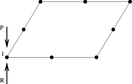
Figure 148 represents the upper surface of a plate of size 1 x 1 x 0.1, modeled by just one C3D20R element. Only the upper face of the element is shown. Suppose the user has fixed all nodes belonging to this face in loading direction. In node 1 an external point loading is applied of size P. Since this node is fixed in loading direction, a reaction force of size R=P will arise. The size of the total force, i.e. the point loading plus the reaction force is zero. This is what the user will get if RF is selected for this node.
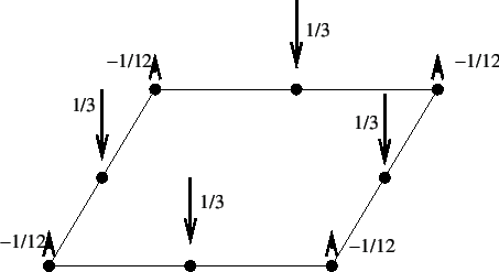
Figure 149 shows the same face, but now the upper surface is loaded by a pressure of size 1. Again, only one C3D20R element is used and the equivalent point forces for the pressure load are as shown. We assume that all nodes on the border of the plate are fixed in loading direction (in this case this means all nodes, since all nodes are lying on the border). Therefore, in each node a reaction force will arise equal to the loading force. Again, the total force in each node is zero, which is the value the user will get by selecting RF on the *NODE PRINT, *NODE FILE or *NODE OUTPUT card.
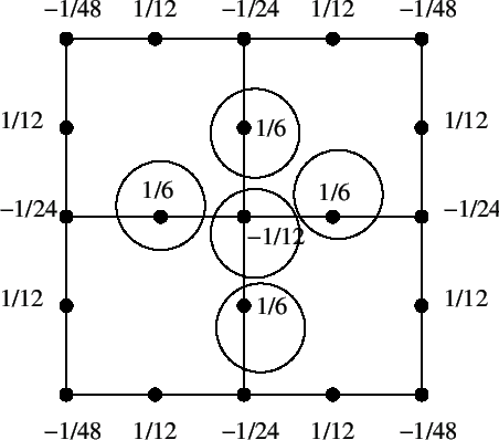
Now, the plate is meshed with 4 quadratic elements. Figure 150 shows a view from above. All borders of the plate are fixed and the numbers at the nodes represent the nodal forces corresponding to the uniform pressure of size 1. Suppose the user would like to know the sum of the external forces at the border nodes (e.g. by selecting RF on a *NODE PRINT card with parameter TOTALS=ONLY). The external forces are the sum of the reaction forces and the loading forces. The total reaction force is -1. The loading forces at the border nodes are the non-circled ones in Figure 150, summing up to 5/12. Consequently the sum of the external forces at the border nodes is -7/12.
By selecting an even finer mesh the sum of the external forces at the border nodes will approach -1.
Summarizing, selecting RF gives you the sum of the reaction forces and the loading forces. This is equal to the reaction forces only if the elements belonging to the selected nodes are not loaded by a *DLOAD card, and the nodes themselves are not loaded by a *CLOAD card.